WebGPU Compute API in VTK

Following previous blog posts (WebGPU in VTK Desktop & Rendering large numbers of actors) on WebGPU in VTK, VTK now offers access to a new perk of modern rendering, namely the possibility to offload computations from the CPU to the GPU using WebGPU compute shaders. These functionalities will be available in VTK 9.4 or later.
Contrary to the typical fragment or vertex shader, compute shaders do not belong to the rendering pipeline and can be used without ever having to display anything. This makes compute shaders the perfect candidates for massively parallel GPGPU (General Purpose GPU) tasks, related or not to rendering. They can take arbitrary data as input and output arbitrary data as well.
Taking advantage of the parallel processing power of GPUs can enable very interesting speedups depending on the use case.
Design Philosophy
The VTK WebGPU Compute API was designed to be easy to use while not being restrictive on the range of applications that can be designed with it. Most importantly, the compute API abstracts away the complexity that resides in the management of the WebGPU Device and Adapter objects as well as the creation and management of WebGPU bind groups and bind group layouts. This effectively translates into the creation and usage of buffers and textures (or other GPU objects) being far easier than if it had to be done in native WebGPU while not compromising on the performance.
The Compute API has thus been designed around two main objects: the vtkWebGPUComputePipeline and the vtkWebGPUComputePass.
Compute passes are the core of the API. They are the objects that dispatch the work to the GPU given a shader and the data it needs to operate. The data is fed to the compute pipelines through objects such as vtkWebGPUComputeBuffer or vtkWebGPUComputeTexture.
A compute pipeline orchestrates the execution of one or multiple compute passes. This concept of pipeline allows chaining compute passes one after the other, possibly reusing the output of one pass as the input to another pass without having to go through the CPU (which would be a performance killer). Also note there always needs to be at least one compute pipeline, even if only one compute pass is used within that pipeline.
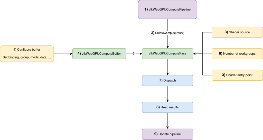
Dispatch() + Read() operationsIn some more details, this is how you would use the API:
- Create a
vtkWebGPUComputePipeline(documentation) - Obtain a compute pass from this compute pipeline with
vtkWebGPUComputePipeline::CreateComputePass() - Set its shader source code and entry point (more details in the next section)
- Create the
vtkWebGPUComputeBuffers(documentation) that contain the data manipulated by the compute pass - Add the buffers to the compute pass
- Set the number of workgroups.
- Dispatch the compute pass
ReadBufferFromGPU()to add a read request to the pipeline that will be executed whenUpdate()will is called.Update()the pipeline so that all the commands are executed (compute passDispatch()as well as reading the results back on the CPU)
These steps from 1) to 9) will be referenced in the following snippets of code to make it easier to follow.
Frustum Culling
To illustrate, let’s dive into a concrete example with the case of frustum culling.
Frustum culling is an algorithm that, given some bounds (which can be bounding boxes or bounding spheres), determines whether these bounds lie within or outside the view frustum of the camera looking at the scene. The goal is to avoid sending objects that are not visible to the GPU.

The frustum culling algorithm has 2 inputs:
- The bounds that need to be tested
- The view-projection matrix of the camera
And 2 outputs:
- How many objects passed the culling test
- The indices of the objects that passed the culling test
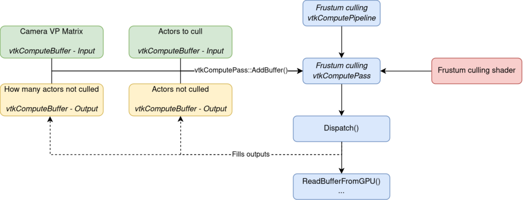
In terms of code, this is all orchestrated through 9 steps.
The first requirement is to create the compute pipeline that will manage our compute pass. The compute pass is then created directly from that compute pipeline and it is that creation step that associates the compute pass with the pipeline.
// Step 1)
vtkNew<vtkWebGPUComputePipeline> frustumCullingPipeline

// Step 2)
vtkSmartPointer<vtkWebGPUComputePass> frustumCullingPass = frustumCullingPipeline->CreateComputePass();
With the compute pass created, it needs to be given a shader (written in the WGSL language for WebGPU) and an entry point. The entry point of the shader is the equivalent of the main function in a regular C++ application. It is the starting point of your shader code when it is invoked.
// Step 3)
frustumCullingPass->SetShaderSource(FrustumCullingShader);
frustumCullingPass->SetShaderEntryPoint("frustumCullingEntryPoint");
The next step is to create and configure the buffers that will contain the data used by the shader. In the case of the frustum culling algorithm, 4 buffers are needed:
The buffer is given the (0, 0) group/binding combination. This is an arbitrary choice but it needs to be unique. No buffers can share the same group/binding pair.
- [in] The view-projection matrix of the camera
- [in] The bounds that need to be tested
- [out] The indices of the objects that passed the culling test
- [out] The number of objects that passed the culling test
// Step 4)
vtkNew<vtkWebGPUComputeBuffer> inputBoundsBuffer;
inputBoundsBuffer->SetGroup(0);
inputBoundsBuffer->SetBinding(0);
inputBoundsBuffer->SetMode(vtkWebGPUComputeBuffer::BufferMode::READ_ONLY_COMPUTE_STORAGE);
inputBoundsBuffer->SetDataType(vtkWebGPUComputeBuffer::BufferDataType::STD_VECTOR);
inputBoundsBuffer->SetData(inputBounds);
Because the buffer that contains the bounds of the objects will only be read by the shader, it is configured with the READ_ONLY_COMPUTE_STORAGE buffer mode.
The other buffers are configured analogously, taking care to use the proper buffer mode depending on how we plan to use the buffer. For example, the outputCountBuffer is set with the READ_WRITE_MAP_COMPUTE_STORAGE because we want to be able to copy it to the CPU from the GPU (hence the required MAP usage).
vtkNew<vtkWebGPUComputeBuffer> outputCountBuffer;
// ...
// Configuration analogous to inputBoundsBuffer
// ...
// Except for the buffer mode that must be READ_WRITE_MAP_COMPUTE_STORAGE
// because we're going to want to read that buffer back to the CPU (and the binding/group that must all be different)
outputCountBuffer->SetMode(vtkWebGPUComputeBuffer::BufferMode::READ_WRITE_MAP_COMPUTE_STORAGE);

vtkNew<vtkWebGPUComputeBuffer> outputIndicesBuffer;
// ...
// Configuration ...
// ...

vtkNew<vtkWebGPUComputeBuffer> viewProjMatBuffer;
// ...
// Configuration ...
// …
With the buffers configured, they can now be added to the compute pass. We’re going to keep the indices returned by the AddBuffer() method as they will be needed later when we’ll want to read the data of the buffer or update/resize the buffer.
// Step 5)
int inputBoundsBufferIndex = frustumCullingPass->AddBuffer(inputBoundsBuffer);
int outputObjectCountBufferIndex = frustumCullingPass->AddBuffer(outputCountBuffer);
int outputIndicesBufferIndex = frustumCullingPass->AddBuffer(outputIndicesBuffer);
int cameraViewProjMatrixBufferIndex = frustumCullingPass->AddBuffer(viewProjMatBuffer);
With the pipeline configured, we must still specify how many workgroups to dispatch. Workgroups are groups of threads which execute your shader code concurrently. Workgroups must have a size (typically a multiple of 32 for performance reasons) and you decide how many workgroups to launch. You typically want to launch enough workgroups to cover the entire range of your data.
We have nbBounds bounds to cull. Our shader uses workgroups of size 32 (see the shader code snippet below). This means that we need nbBounds / 32 groups to ensure that we have one thread per bounds to cull. Ceiling the result is necessary so that non-multiple of 32 bounds counts are still properly covered.
// Step 6)
int groupsX = std::ceil(nbBounds / 32.0f);
frustumCullingPass->SetWorkgroups(groupsX, 1, 1);

// Step 7)
frustumCullingPass->Dispatch();
After the culling pass is dispatched, we’ll want to read the results back onto the CPU. This is done thanks to the ReadBufferFromGPU() function. It takes the index of the buffer as input as well as a callback and some data to pass to the callback.
// Step 8)
frustumCullingPass->ReadBufferFromGPU(outputObjectCountBufferIndex, outputObjectCountMapCallback, &mapDataObjectCount);
frustumCullingPass->ReadBufferFromGPU(outputIndicesBufferIndex, outputObjectIndicesMapCallback, &mapDataIndices);

// Step 9)
frustumCullingPipeline->Update();
After the Update() call, the results are now available on the CPU and can be used to discard non-visible objects from the rendering process.
// Bounds of the object to cull
@group(0) @binding(0) var<storage, read> inputBounds: array<Bound>;
// How many bounds were not culled
@group(0) @binding(1) var<storage, read_write> outputCount: atomic<u32>;
// Output list of the indices non culled bounds
@group(0) @binding(2) var<storage, read_write> outputIndices: array<u32>;
// View-projection matrix of the camera whose frustum is going to cull the objects
@group(0) @binding(3) var<uniform> viewProjectionMatrix: mat4x4f;

// The size of the workgroups is chosen here
@compute @workgroup_size(32, 1, 1)
fn frustumCullingEntryPoint(@builtin(global_invocation_id) id: vec3<u32>)
{
   …
}
Snippet of how the bindings/groups/workgroup size of the frustum culling shader are configured in the shader.
Another detail that needs to be handled is when the bounds of the objects or view-projection matrix of the camera changes. We will need to reupload the data to the buffer so that the shader executes on the proper data. This can be easily done with a simple one-liner:
frustumCullingPass->UpdateBufferData(inputBoundsBufferIndex, newBoundsData);We may also need to resize buffers if the number of objects in the scene changes for example. Here again, this can be done by a single call.
frustumCullingPass->ResizeBuffer(inputBoundsBufferIndex, newNumberOfObjects * 6 * sizeof(float));The compute API then internally handles the nasty details.
Conclusion
The frustum culling presented here has been implemented in VTK using the WebGPU Compute API and you can check out the implementation if more specific details are needed.
In a next blog post, we’ll have a look at the hierarchical occlusion culling algorithm implemented with the WebGPU Compute Shaders API. This future blog post will include exciting performance benchmarks and comparisons.
As new perspectives, compute shaders could also be used to speed up the rendering of point clouds and for gaussian splatting rendering. Compute shaders also have a use for non-rendering tasks such as scientific computations.
This work is an internal effort of Kitware Europe.
Look forward to performance benchmarks. Awesome work!