PBR Journey Part 2 : Anisotropy model with VTK


Introduction
In our previous post on the new features of the PBR shading in VTK 9.0, we introduced the HDR environment and how to use it to enhance the realism of the rendering in VTK.
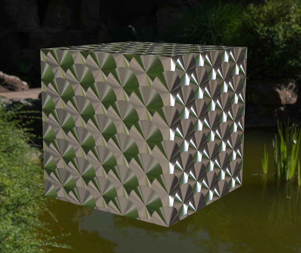
We are happy to announce that the PBR shader now supports rendering of anisotropic materials like brushed metals or compact disks. Anisotropic materials have different reflecting properties that depend on the direction of the anisotropy, which is defined by the tangent of the geometry and its rotation. The more anisotropic a material is, the more its lighting is influenced by its direction. Thus, it is necessary to have normals and tangents in order to have an anisotropic material.
Parameters
This model adds two parameters to vtkProperty that can be used by the vtkPolyDataMapper to configure the anisotropy :
- Anisotropy: The strength of the anisotropy (between 0.0 and 1.0). 0.0 means an isotropic material, 1.0 means a fully anisotropic material.

- AnisotropyRotation: Rotates the direction of the anisotropy (ie. the tangent) around the normal counter-clockwise (between 0.0 and 1.0). A value of 1.0 corresponds to a rotation of 2 * PI.

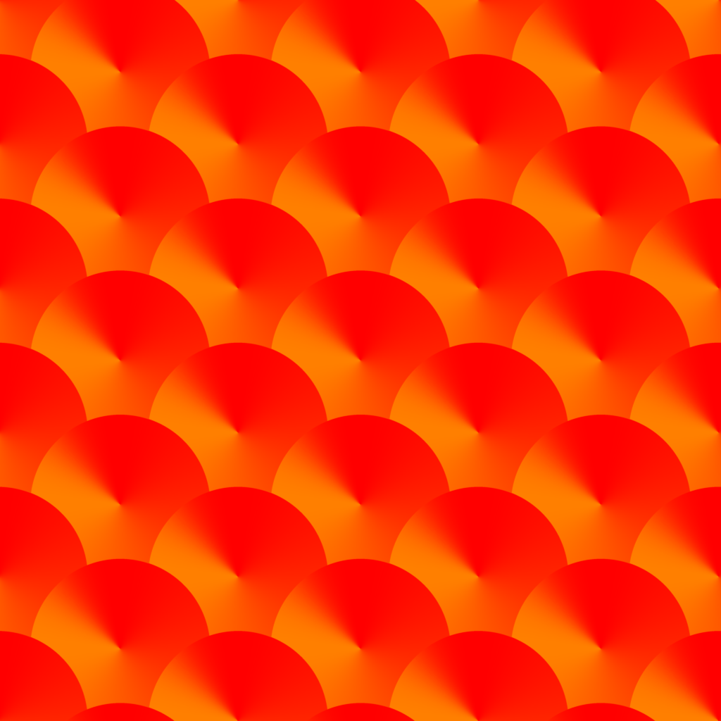
It is possible to define the anisotropy strength as well as the anisotropy rotation in a texture to create more complex materials. The red channel holds the anisotropy strength and the green channel holds the anisotropy rotation. The blue channel is discarded. One can add this anisotropy texture to the data by using vtkProperty::SetAnisotropyTexture(texture). We provide the anisotropy texture used to render the cube in figure 1 in the figure below.

Example
In the example below, we render the same cube as depicted in figure 1, using the anisotropy texture in figure 4.
vtkNew<vtkCubeSource> cube;
vtkNew<vtkTriangleFilter> triangulation;
triangulation->SetInputConnection(cube->GetOutputPort());

// Compute the data tangents needed for anisotropy
vtkNew<vtkPolyDataTangents> tangents;
tangents->SetInputConnection(triangulation->GetOutputPort());

vtkNew<vtkPolyDataMapper> mapper;
mapper->SetInputConnection(tangents->GetOutputPort());

// Load the anisotropy texture
vtkNew<vtkPNGReader> anisotropyTexReader;
anisotropyTexReader->SetFileName("pathToYourAnisotropyTexture.png");
vtkNew<vtkTexture> anisotropyTex;
anisotropyTex->InterpolateOn();
anisotropyTex->SetInputConnection(anisotropyTexReader->GetOutputPort());

// Load the normal texture
vtkNew<vtkPNGReader> normalTexReader;
normalTexReader->SetFileName("pathToYourNormalTexture.png");
vtkNew<vtkTexture> normalTex;
normalTex->InterpolateOn();
normalTex->SetInputConnection(normalTexReader->GetOutputPort());

// Create the actor
vtkNew<vtkActor> actor;
actor->SetMapper(mapper); actor->GetProperty()->SetInterpolationToPBR();
actor->GetProperty()->SetMetallic(1.0);
actor->GetProperty()->SetRoughness(0.1);

// Set anisotropy and anisotropyRotation
// to 1.0 as they act as multipliers with texture value
actor->GetProperty()->SetAnisotropy(1.0);
actor->GetProperty()->SetAnisotropyRotation(1.0);

// Set the normal and anisotropy texture
actor->GetProperty()->SetNormalTexture(normalTex);
actor->GetProperty()->SetAnisotropyTexture(anisotropyTex);

// Finally, add the actor to the renderer
renderer->AddActor(actor);
What’s next
Anisotropy model will be available in ParaView 5.10 and in nightly builds.
In the upcoming part III of our PBR journey we will introduce a clear coat model that simulates an isotropic layer on top of the object. Stay tuned !
Acknowledgements
This work is funded by an internal innovative effort of Kitware Europe.