Detect, locate and seize with VeloView: Actemium and Kitware demonstrate the industrial capabilities of pattern recognition in Lidar point-clouds
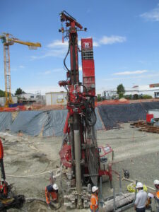
Kitware and Actemium are pleased to present their fruitful collaboration using a Lidar to detect, locate and seize objects on a construction site for semi-automated ground drilling. Actemium’s overall mission is to automate the drilling process of pile foundations for buildings, in which multiple hollow tubes are used, and then filled with concrete.
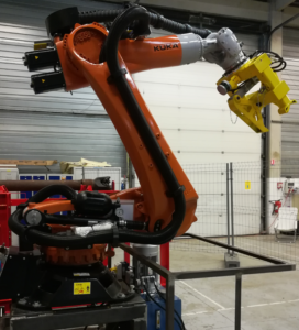
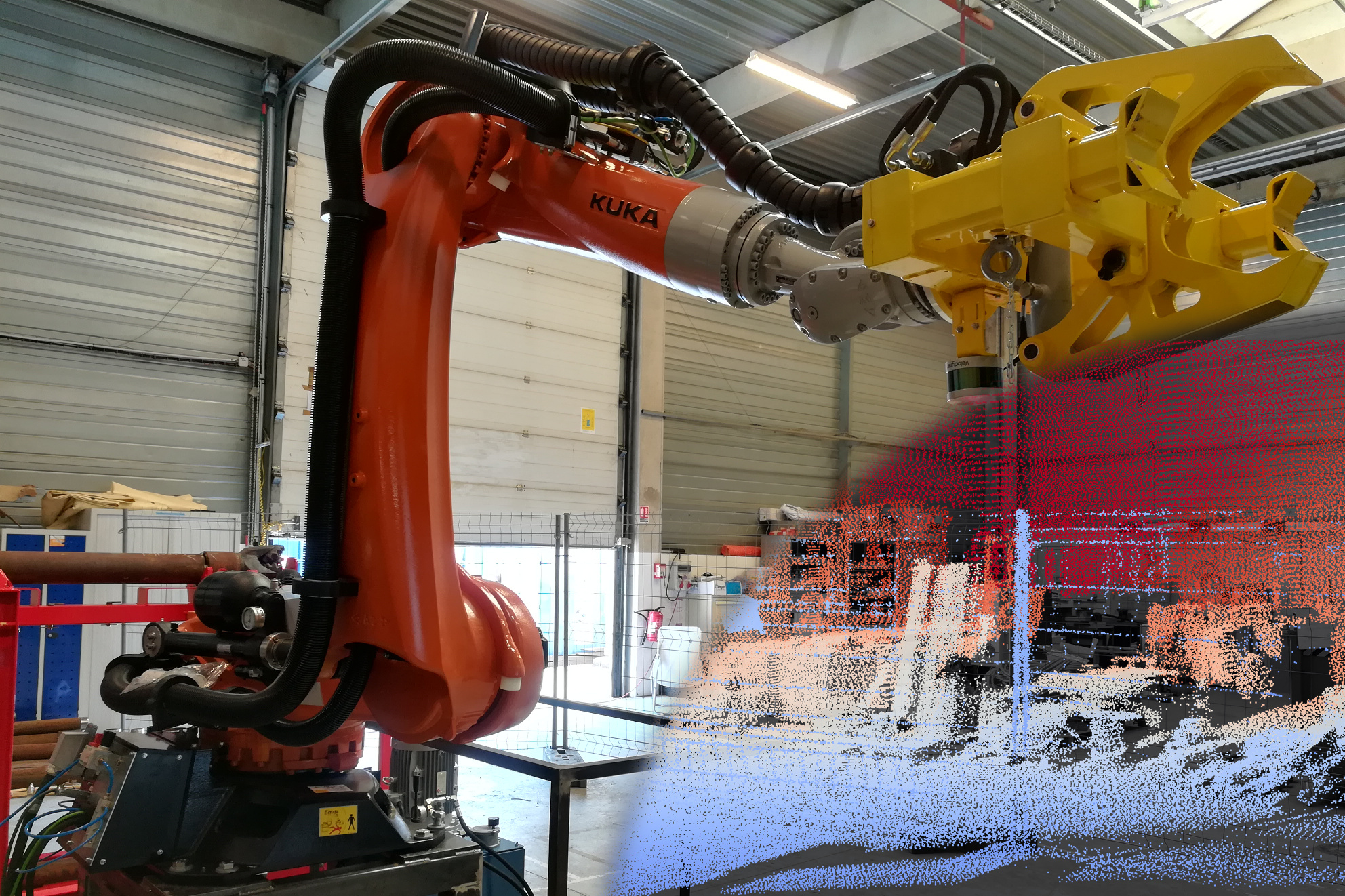
The collaboration aims to automate the drilling process by replacing the manual addition of drilling tubes with a semi-automatic one. A KUKA robot arm -driven by Kitware vision algorithms- has to put additional tubes into the driller head for it to continue drilling down. Actemium chose a Velodyne Lidar sensor as an input, and asked Kitware to make the pattern recognition algorithms based on VeloView.
VeloView is a free open-source Paraview-based application developed by Kitware. It is designed to visualize and analyse raw data from the Velodyne LiDAR sensors as 3D point cloud. Thanks to its open-source nature, customer-specific versions are regularly developed, containing specific enhancements such as:
– Drivers: IMU, GPS or any specific hardware
– Algorithms: point cloud filtering and analysis, deep learning for object recognition (pedestrians, traffic signs, vehicles, …), semantic classification, SLAM for automotive or UAV, dense 3D reconstruction, …
– Custom graphical interface to simplify customer processes, or to show the live detection of objects or pedestrians
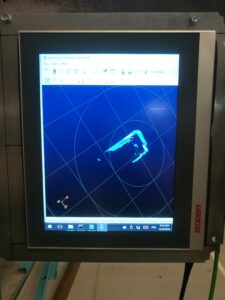
Kitware’s task was to first scan the scene at the beginning of a new pile drilling, in order to detect the driller’s position and orientation. Secondly, for each tube addition, we need to locate the head of the previous tube. Finally, we send those information for the robot to move the new tube in position.
A high density point cloud of the scene is acquired, by moving the LiDAR sensor to compensate for its sparse nature. Here a VLP-16 is used (2 degrees of vertical angular resolution between each of the 16 rotating laser-beams, and up to 120m range with 2 cm accuracy). Kitware programmed the KUKA arm relative motion computation and merged the acquired point clouds into the KUKA’s coordinate system.
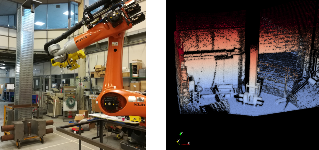
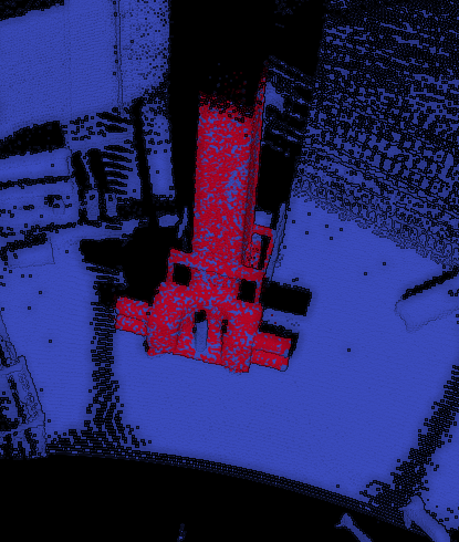
Once the whole scene is fully scanned (in 20 seconds), a pattern recognition algorithm using drillers prior models is launched to detect and locate the driller.
The driller location parameters are then transmitted to the robot. With the driller itself being located, the system can move on to the second phase: decide how to stack the tubes. For each new tube, the robot will launch a “tube scan” phase to acquire a high density point cloud around the location where the previous tube should have been placed.
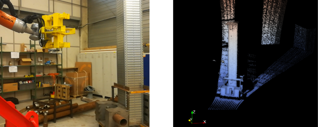
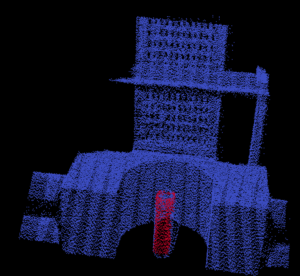
Then, within this point cloud, a second pattern recognition algorithm is launched, looking for a cylinder model to detect and locate the previous tube. The recovered position, angle, length, radius and axis of the tube are transmitted to the robot.
The robot will then place the next tube in position according to the position and orientation transmitted by the vision algorithms. The recovered position accuracy is below half a centimeter.
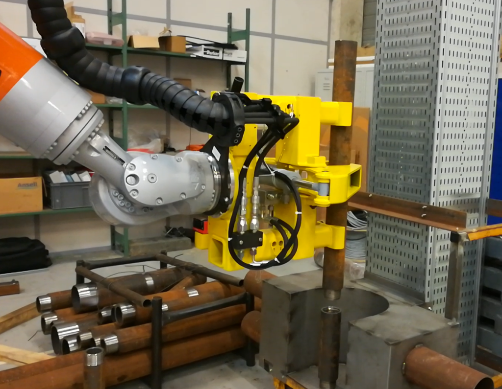
Et voilà, we made the robot arm do it!
It takes now 30 seconds to add a new tube, versus 5 minutes with the previous manual method.
This work was globally funded by Actemium Poissy.

Software development was done by Kitware SAS.

 Bastien Jacquet, PhD is a Technical Leader at Kitware, France.
Since 2016, he promotes and extends Kitware’s Computer Vision expertise in Europe. He has experience in various Computer Vision and Machine Learning subdomains, and he is an expert in 3D Reconstruction, SLAM, and related mathematical tools.
 Pierre Guilbert is a computer vision R&D engineer at Kitware, France.
He has experience in Computer Vision, Machine Learning Classification for medical imagery and image registration in 2D and 3D. He is familiar with 2D and 3D processing techniques and related mathematical tools
Since 2016, he works at Kitware on multiple projects related to multiple-view geometry, SLAM and point-cloud reconstruction and analysis.
Update end of 2024 :
VeloView is not actively maintained anymore, but LidarView, its multi vendor equivalent is still being actively developed. In particular, the ability to create custom applications like the one highlighted in this blog is still very viable. We invite you to check out https://lidarview.kitware.com/ and out latest blogpost on LidarView.
For more information or if you are interested in developing a LidarView based app for a similar (or different), do not hesitate to reach out to us at https://www.kitware.eu/contact/